MSW Gasification Plant at Biratnagar
The MSW gasification plant at Biratnagar is a state-of-the-art facility designed to process 10 tons of municipal waste daily in a 10-hour operational cycle. This innovative plant transforms waste into Refuse-Derived Fuel (RDF) pellets and converts them into syngas for energy generation. The plant operates in two key zones—Zone 1 for waste preprocessing and Zone 2 for gasification and energy production—making it an efficient and sustainable solution to Nepal’s growing waste management challenges.

Zone 1: Preprocessing and RDF Pellet Production Components
1. Loading Conveyor
The loading conveyor is the initial component that handles the raw, washed municipal solid waste (MSW). This conveyor can handle up to 10 tons of waste daily over a 10-hour operational cycle. Its primary function is to automate the loading process, minimizing labor needs while ensuring a consistent flow of materials into the system.
2. Inclined Pre-Shredder Feeder Conveyor
Once the waste enters the system, it moves through the inclined pre-shredder feeder conveyor, which lifts and feeds the material at a controlled pace into the primary shredder. This conveyor is vital for maintaining the smooth flow of material, especially for handling bulky and diverse waste types like plastics, textiles, and paper. It optimally feeds the material, allowing for an even load distribution throughout the processing stages.
3. Primary Shredder (Double Shaft)
The primary shredder, a double-shaft shredder, is responsible for breaking down large waste pieces into smaller, more manageable sizes, typically reducing them to less than 100 mm. With a processing capacity of up to 2 tons per hour, the shredder is essential for reducing the volume of waste, enabling further processing such as drying and pelletization.
4. Inclined Transfer Conveyor
After shredding, the material is transported via the inclined transfer conveyor, which continuously moves the shredded material from one stage to the next, ensuring that the system operates smoothly. This component helps maintain a steady workflow, delivering the shredded material efficiently to the feeder chute.
5. Feeder Chute
The feeder chute is an important component that directs the shredded waste into the drum dryer. It ensures that the material is fed evenly and consistently, preventing jams or blockages that could slow down the processing line. This is crucial for maintaining continuous operation without disruptions.
6. Drum Dryer
The drum dryer is used to remove moisture from the waste material, an essential step before pelletization. By drying the material, the moisture content is reduced, making the waste better suited for forming RDF (Refuse-Derived Fuel) pellets. This step is critical for optimizing the fuel potential of the final product. The drum dryer ensures that the material reaches the ideal moisture level for further processing.
7. Z-Inclined Conveyor with Magnetic Separator
The Z-inclined conveyor features a magnetic separator that extracts any ferrous metals from the waste stream after drying. This ensures that only non-metallic materials proceed further in the process, improving the quality and purity of the RDF pellets and preventing contamination in the final product.
8. Bucket Conveyor
The bucket conveyor elevates the waste material vertically, transferring it from one stage to the next. After passing through the magnetic separator, the material is lifted by this conveyor to the next stage of processing, ensuring that the waste moves efficiently through the system without losing pace.
9. Fine Shredder
The fine shredder further refines the waste material, reducing it to smaller, more uniform particles, essential for the production of high-quality RDF pellets. This step is crucial for achieving the desired particle size, making the material more compact and suitable for pelletization.
10. Screw Feeding Conveyor
Once the material is finely shredded, the screw feeding conveyor takes over, feeding the fine material into the RDF pellet maker at a controlled rate. This ensures that the material flows smoothly and evenly into the pelletizing process, without causing blockages or inconsistencies.
11. Dust Collector
The dust collector is responsible for capturing dust and fine particles generated during the shredding and pelletizing processes. It ensures that the environment remains clean and prevents airborne dust from interfering with the pelletizing process, maintaining both the safety and efficiency of the system.
12. RDF Pellet Maker
The RDF pellet maker is where the fine, shredded waste is compacted into RDF pellets. These pellets are the primary output product of the system, ready to be used as a fuel source for the gasification unit or for other energy recovery processes. The pellet maker is key to converting waste into a valuable energy source, improving the overall efficiency of the waste-to-energy system.
13. RDF Collection Container
Once the RDF pellets are formed, they are deposited into the RDF collection container. This container is designed to store the pellets until they are ready for use or transport, ensuring that the pellets remain organized and ready for their next phase of processing.
14. Electrical Control Box
The electrical control box regulates the entire system, ensuring that each component functions properly and safely. It allows operators to monitor and manage the workflow of the system, ensuring that every stage operates smoothly and efficiently, which is vital for maintaining overall system performance.

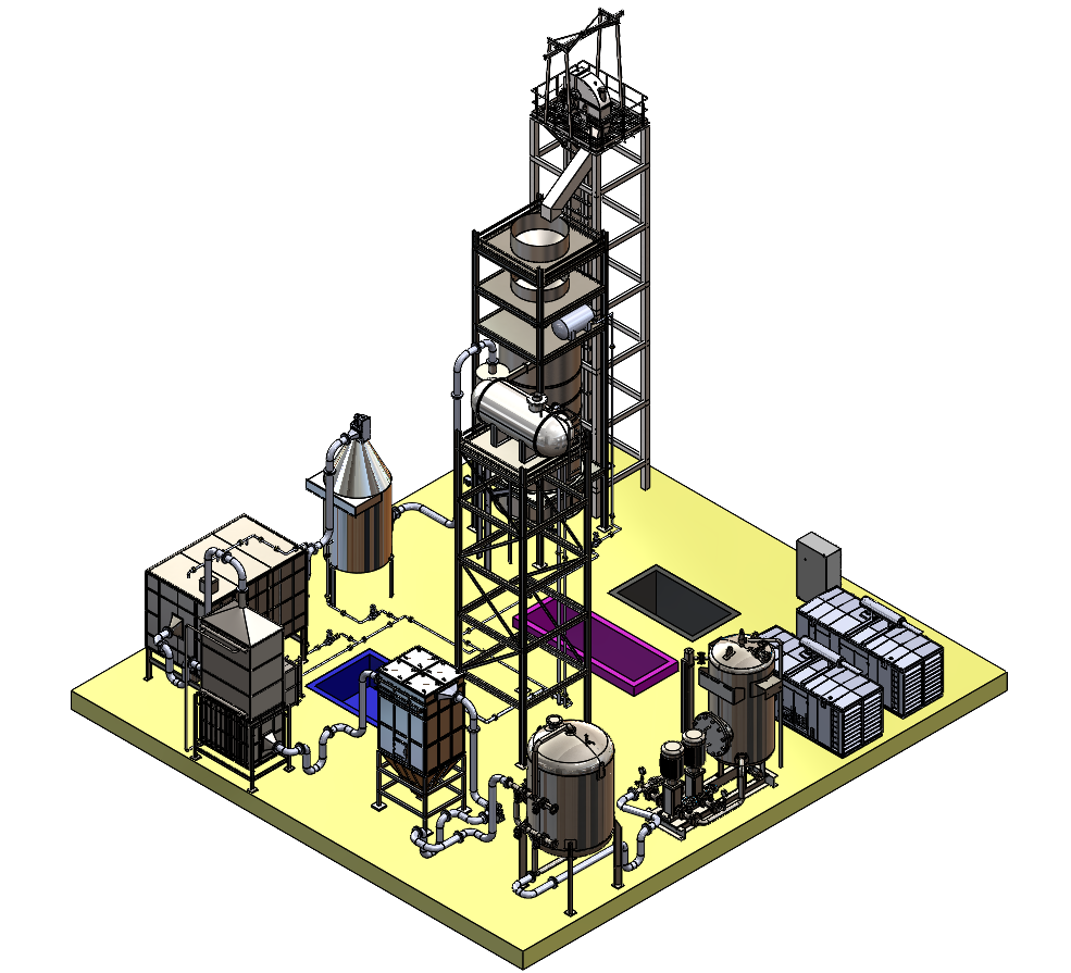
Zone 2: Gasification Process Components
1. Bucket Lift
The bucket lift is used to transport RDF pellets from Zone 1 to the gasification unit in Zone 2. It ensures that the pellets are lifted efficiently, feeding the system with a continuous supply of fuel for the gasification process. This lift ensures a smooth transition of material from preprocessing to energy generation.
2. Gasification Unit
The gasification unit is the heart of the waste-to-energy process. Here, RDF pellets undergo gasification in a low-oxygen environment at temperatures between 900-1100°C. The unit includes several key sub-components:
- Hopper Feeder: Loads the RDF into the gasifier.
- Burner: Provides the necessary heat for the gasification process.
- Gasification Body: The core chamber where the RDF is processed.
- Rotary Grate: Moves the RDF through different temperature zones: drying, pyrolysis, oxidation, and reduction, ensuring efficient conversion of waste to syngas.
- Forced Draft (FD) Fan/Blower: Supplies the required airflow to support combustion and gasification.
3. Ash Removal Conveyor
The ash removal conveyor removes the ash produced during the gasification process. It ensures continuous operation by clearing out the residue, which prevents the system from becoming clogged and ensures that the gasifier functions without interruptions.
4. Cyclone Separator
The cyclone separator separates large particulates from the syngas after it exits the gasifier. This component ensures that only clean gas moves forward in the process, improving the efficiency of the downstream purification stages.
5. Wet Scrubber (Venturi)
The wet scrubber removes fine particles and contaminants from the syngas. By passing the gas through a water spray, it traps pollutants, ensuring that the syngas is as clean as possible before it moves to the next stages.
6. Wet Electrostatic Precipitator (WESP)
The WESP uses electrical charges to capture any remaining particulates from the syngas. This component plays a critical role in ensuring that the gas is free from harmful pollutants, making it suitable for energy generation.
7. Condenser Unit
The condenser unit cools the syngas after it has been cleaned, removing moisture and making it denser. This step enhances the gas’s energy potential, making it more efficient for use in power generation.
8. Water Tank and Filtration
The water tank and filtration system provide clean water for the wet scrubber and other processes that require water. This ensures that the system operates efficiently and that the water used in gasification is free from impurities.
9. Baghouse Filter
The baghouse filter removes any remaining dust particles from the syngas before it is sent for compression or use. This ensures that the gas is free from any particulates that could damage equipment or interfere with energy generation.
10. Active Carbon Filter
The active carbon filter removes sulfur and other unwanted compounds from the syngas. This ensures that the gas is purified and suitable for use in the generator set, contributing to cleaner energy production.
11. Syngas Compressor
The syngas compressor pressurizes the cleaned syngas, making it suitable for storage or immediate use in energy generation. This compressor ensures that the gas can be stored efficiently in the buffer tank for use in the generator set.
12. Buffer Tank
The buffer tank stores compressed syngas until it is needed by the generator set. This tank ensures that there is always a ready supply of fuel available for electricity production.
13. Generator Set
The generator set uses the syngas to generate electricity or heat. This is the final step in the process, converting waste into a useful energy form that can be used on-site or added to the local grid. The generator set is designed to efficiently convert syngas into electrical energy by combusting a mixture of carbon monoxide, hydrogen, methane, and nitrogen. This combustion process generates high-temperature gases that drive either a turbine or an internal combustion engine, transforming thermal energy into mechanical energy, which is then converted into electrical power.
The efficiency of the generator is influenced by the composition of the syngas and its lower heating value (LHV), which is calculated at approximately 5.3 MJ/Nm³. The syngas composition consists of 22% carbon monoxide, 6% carbon dioxide, 14% hydrogen, 3% methane, and 55% nitrogen, with a volume flow rate of 1640 Nm³/h. The generator is capable of producing 733 kW of power and operates with two generators, each with a 500 kVA capacity. It is designed to run in dual fuel burning mode, utilizing both syngas and diesel for optimal efficiency depending on fuel availability. The integrated PLC-based control panel enables real-time monitoring and auto-synchronization, improving system performance. Additionally, the electric starter with battery backup ensures reliable ignition and operation, even during power outages, making the generator set a robust and adaptable solution for continuous power generation.
Summary of MSW Gasification Plant Data
The plant processes 10 tons of MSW daily over 10 hours, utilizing its various components across two operational zones to convert waste into energy. In Zone 1, with a size of 24×7 meters, the plant handles the preprocessing of MSW, which includes shredding, drying, and pelletizing. The equipment here, including the loading conveyor, pre-shredder feeder conveyor, primary shredder, drum dryer, and RDF pellet maker, works together to convert raw waste into RDF pellets. This zone consumes 429.5 kW of energy, powering the shredding and drying processes.
In Zone 2, occupying 30×28 meters, the RDF pellets undergo the gasification process. The key components in this zone include the gasification unit, rotary grate, and forced draft fan, which together break down the RDF into syngas. This zone consumes 53.5 kW of power. The syngas produced is cleaned and pressurized, with components like the cyclone separator, wet scrubber, WESP, and syngas compressor ensuring its purity and compressing it for use. The gasification system generates 733 kW of energy, resulting in a net energy surplus of 250 kW after considering the energy consumption across both zones.